Showing posts with label SAN. Show all posts

How to increase the provisioned size of a volume in Pure Flash Array storage using CLI


In a "storage administrator" profession, it is quite common to receive requests for space
expansion/increase on SAN volumes. Pure Flash Array has both CLI and GUI options available to increase provisioned space of a storage volume. in this article, we will be exploring the possible CLI options for the same. 

How to Connect Volume to a Host in pure Flash Array

Volumes must be connected to hosts for the hosts to read and write data on them. To make SAN volumes available to a host after a host has been created and WWNs are added on Pure Flash Array, we must establish a connection between the host and volumes. 

How to add a host in Pure Flash Array storage using CLI

 Pure Flash Array storage uses the "host" option/attribute to define server-storage relation. A host can be configured in Pure Flash array by using GUI as well as CLI.  In this article, we will be exploring the CLI option to configure/add a host in Pure Flash Array storage. To create a host entry in Pure Flash Array Storage, we use the "purehost create" command. 

How to create volume in pure storage using CLI

 To create volumes on Pure Flash Array we use Purevol create Command. The purevol create command creates one or more FlashArray virtual storage volumes with the --size parameter set.

How to find Serial number of Pure Storage Array using CLI

 To find the serial number and hardware information of the Pure Flash array, we use "purehw list" command. The purehw list command returns information on array hardware components. The output is mostly useful for troubleshooting hardware issues.

HPE StoreVirtual configuration using CMC -Step By Step Guide

In our previous posts we discussed about installation and initial configuration of Storevirtual nodes using CMC(Centralized Management Console). In this article we will see management group and cluster configuration using CMC.

How to generate license for HP Storage Products

Whenever we purchase a new storage equipment, before using that, we need to activate the license associated with the device. This is applicable for all products irrespective of vendors. HP also has a mechanism through which the customer can activate the licenses associated with their storage product.

HP 3PAR StoreServ 8000 and 20000 comparison

Recently HP has announced new portfolio for their trademark 3PAR storage arrays with improvement in specification and performance. Based on this latest additions, this storage is setting the benchmark for other vendors and planning to hit the number one position. This new series named 8000 and 20000  will replace the existing 7000 and 10000 series respectively and HP has already started shipping the new StoreServ models to their customers.


Brocade configuration restore procedure (How To)

It is a real nightmare for all SAN admins when they think about restoring switch configuration. Though it is rare case to restore the switch configuration under normal circumstances, we should be aware about the process and precautions which need to follow while restoring the configuration backup. When we restore a configuration file, we are actually overwriting the existing configuration with a previously saved backup configuration file. While we are restoring a configuration backup, make sure the FOS and switch model is compatible so that we won't encounter further issues while restoring the configuration.

Brocade configuration backup procedure (How To)

Though it is a proactive measure, it is important to configure and take backup of your SAN switch configuration to avoid any unexpected outages to your business. We have been working on Brocade SAN for quite some time now and we don't see any better tool than it's native config backup command configupload/configdownload. As part of standard configuration maintenance procedures, Brocade also recommends to keep backup of  important configuration data for every switch on a host computer server as a safety measure.
The configshow -all output will show you the configuration information of a switch, while configupload -all command will help you to save your switch information along with all details which will help you to recover the system.

Configuration details which we capture using configupload -all has two main sections, chassis section and switch section. while chassis sections defines configuration data for chassis components that affect the entire system, switch section contains zoning information, boot configuration etc.

We should keep individual backup files for all switches with in a fabric and the config-file has to be uploaded to a site from where we can download it easily. we basically use the management server itself for configuration backup. The configupload command, by default, only uploads the switch context configuration for the logical switch context in which the command is executed.

As a prerequisite, make sure that the switch can reach the management server and FTP is enabled on that server. Once you are done with the pre-checks, the actual process begins,

1.Connect to the switch and log in using an account with admin permissions(default is admin).
2.Enter configUpload command.

Example of configUpload on a brocade SAN switch,
Switch01:admin> configupload
Protocol (scp, ftp, sftp, local) [ftp]:
Server Name or IP Address [host]: 192.168.1.10
User Name [user]: sanadmin
Path/Filename [/config.txt]: switchConfigbkp.txt
Section (all|chassis|FID# [all]):
Password:
configUpload complete
The above example was an interactive mode. if you want the upload in a non-interactive manner, try the following.

Switch01:admin> configupload -ftp 192.168.1.10,sanadmin,switch-conf_backup.cfg, password
configUpload complete: All config parameters are uploaded

Store a copy of the switch configuration information in a safe place for future use. 

Remove HP P9500 ldev reservation

Have you ever faced issues while deleting an ldev from HP XP or P9500 storage arrays? if yes, this is the right spot where you can find a solution. Most of the time the issue is related to lun reservation either caused by system software or cluster resources and you may not be able to delete it until you remove the reservation. There is an easy method to remove the lun reservation by using a utility which gets installed along with the HP DSM multipathing software, which we install for effectively load balancing the disk.
The utility is called HPprutil.exe, which is usually get installed under C:\Program Files\Hewlett-Packard\HP MPIO DSM\XP DSM\X86 along with HP DSM software.


The command HPPRUTIL DEVICES displays the type of reservation active on each device.

C:\Program Files\Hewlett-Packard\HP MPIO DSM\XP DSM\X86>HPprutil.exe devices
The requested operation is in progress.Please wait......
Device#  Device Name               Scsi Address    Reservation   NT Disk#
--------------------------------------------------------------------------
1        HP      OPEN-V-CM            1.0.0.0           None         Disk 1
2        HP      OPEN-V-CM            1.0.1.1           None         Disk 2
3        HP      OPEN-V-CM            1.0.2.0           None         Disk 3
4        HP      OPEN-V-CM            1.0.2.1           None         Disk 4
5        HP      OPEN-V               1.0.2.4           None         Disk 5
6        HP      OPEN-V               0.0.2.10          PR           Disk 6

The following are the types of reservation:

    1. SCSI       - Indicates a SCSI reservation on the device.
    2. PR         - Indicates a persistent reservation on the device.
    3. None       - Indicates the device is not reserved.
    4. SCSI/PR    - Indicates that a SCSI or persistent reservation exists on the device.

In the above example, you could see that device#6 has persistent reservation and if you try to remove the ldev using management console, it will fail. We can clear the reservation using HPPRUTIL command.

Let see how!

Command to Display and remove reservations present on devices are as follows,

HPPRUTIL DEVICES              : Displays details of reservation on devices.
HPPRUTIL CLEAR DEVICE=<#>     : Clears the reservation present on device #

open command prompt and change the directory to the source where the HPPRUTIL is located and use HPPRUTIL CLEAR DEVICE command.

C:\Program Files\Hewlett-Packard\HP MPIO DSM\XP DSM\X86>HPprutil.exe clear device=6
The requested operation is in progress.Please wait......
HPPRUTIL will attempt to clear the reservation on device 6.
Are you sure you want to continue (y/n)? y

Attempting to clear the reservation on device 6...
Successfully cleared the reservation on device.
C:\Program Files\Hewlett-Packard\HP MPIO DSM\XP DSM\X86>

You can see that the lun reservation has been cleared by the command. Run the command HPPRUTIL DEVICES  to verify the status.

C:\Program Files\Hewlett-Packard\HP MPIO DSM\XP DSM\X86>HPprutil.exe devices
The requested operation is in progress.Please wait......
Device#  Device Name               Scsi Address    Reservation   NT Disk#
--------------------------------------------------------------------------
1        HP      OPEN-V-CM            1.0.1.0           None         Disk 1
2        HP      OPEN-V-CM            0.0.0.1           None         Disk 2
3        HP      OPEN-V-CM            0.0.2.0           None         Disk 3
4        HP      OPEN-V-CM            0.0.2.1           None         Disk 4
5        HP      OPEN-V               1.0.2.4           None         Disk 5
6        HP      OPEN-V               0.0.2.10          None         Disk 6
C:\Program Files\Hewlett-Packard\HP MPIO DSM\XP DSM\X86>

Persistent reservation on the device has been removed. You can delete the lun from console without any issues now. 

Brocade SAN switch SNMP configuration and testing(How to Article) Part 2


STEP 4:-
Once the SNMP server IPs are configured and settings are applied, the next step is to verify the settings and do modifications in case required.

To check the SNMP settings, issue the command as below,

switch01:FID128:admin> snmpconfig --show snmpv1
SNMPv1 community and trap recipient configuration:
  [...]
  Community 5: public (ro)
    Trap recipient: 192.168.1.110
    Trap port: 162
    Trap recipient Severity level: 4
  [....]
Note:- Output is truncated

switch01:FID128:admin> snmpconfig --show snmpv3
SNMP Informs = 0 (OFF)
SNMPv3 USM configuration:
User 1 (rw): snmpadmin1
        Auth Protocol: noAuth
        Priv Protocol: noPriv
[...]
SNMPv3 Trap configuration:
Trap Entry 1:     192.168.1.10
    Trap Port: 162
    Trap User: snmpadmin1
    Trap recipient Severity level: 4
[....]
Note:- Output is truncated

Once the configuration is in place, the next step is to identify the traps which has to be forwarded to generate tickets. to perform that task we have to modify the MIB capability of the Brocade swith.

STEP 5:-

The management information base (MIB) is a database of monitored and managed information on a device.For Brocade, there are two main MIB trap choices:
• FibreAlliance MIB trap - Associated with the Fibre Alliance MIB (FA-MIB), this MIB manages SANswitches and devices from any company that complies with Fibre Alliance specifications.
• Brocade-specific MIB trap - Associated with the Brocade-specific Brocade MIB (SW-MIB),manages Brocade switches only

To read in depth please click here

TO view the traps which are currently enabled for a switch, issue the command as below.

switch01:FID128:admin> snmpconfig --show mibcapability
FE-MIB: YES
SW-MIB: YES
FA-MIB: YES
FICON-MIB: NO
HA-MIB: NOFCIP-MIB: NO
ISCSI-MIB: NO
IF-MIB: YES
BD-MIB: NOSW-TRAP: YES
[...]
Note:- Output is truncated.
Observe that, HA-MIB and BD-MIB are turned off here.ideally, this should be enabled to receive status change notifications.

To modify the MIB capabilty for a brocade switch, we have issue snmpconfig command along with the --set option as described below.

switch01:FID128:admin> snmpconfig --set mibcapability
[...]
FE-MIB (yes, y, no, n): [yes]
SW-MIB (yes, y, no, n): [yes]
FA-MIB (yes, y, no, n): [yes]
FICON-MIB (yes, y, no, n): [no]
HA-MIB (yes, y, no, n): [no]
FCIP-MIB (yes, y, no, n): [no]
ISCSI-MIB (yes, y, no, n): [no]
IF-MIB (yes, y, no, n): [yes]
BD-MIB (yes, y, no, n): [no]
SW-TRAP (yes, y, no, n): [yes]
        swFault (yes, y, no, n): [yes]
        swSensorScn (yes, y, no, n): [yes]
        swFCPortScn (yes, y, no, n): [yes]
        swEventTrap (yes, y, no, n): [yes]
                DesiredSeverity: (0..4) [0]
        swFabricWatchTrap (yes, y, no, n): [yes]
                DesiredSeverity: (0..4) [0]
        swTrackChangesTrap (yes, y, no, n): [yes]
        swIPv6ChangeTrap (yes, y, no, n): [yes]
        swPmgrEventTrap (yes, y, no, n): [yes]
        swFabricReconfigTrap (yes, y, no, n): [no]
        swFabricSegmentTrap (yes, y, no, n): [no]
        swExtTrap (yes, y, no, n): [yes]
        swStateChangeTrap (yes, y, no, n): [no]
        swPortMoveTrap (yes, y, no, n): [no]
        swBrcdGenericTrap (yes, y, no, n): [no]
FA-TRAP (yes, y, no, n): [yes]
        connUnitStatusChange (yes, y, no, n): [yes]
        connUnitDeletedTrap (yes, y, no, n): [yes]
        connUnitEventTrap (yes, y, no, n): [yes]
        connUnitSensorStatusChange (yes, y, no, n): [yes]
        connUnitPortStatusChange (yes, y, no, n): [yes]
IF-TRAP (yes, y, no, n): [no] yes
        linkDown (yes, y, no, n): [no] yes
        linkUp (yes, y, no, n): [no] yes
Operation succeeded
Operation succeeded


STEP 6:-
It's time to test the setup. On older firmware versions, to test SNMP forwarding, we normally enable/disable the ports. With the latest versions, we have "snmptraps" which can be used to simulate the error condition.

Let's try it now,

you have to mention the trap name and ip address of the SNMP server while using snmptraps command.

switch01:FID128:admin> snmptraps --send -trap_name cp-status-change-trap -ip_address 192.168.1.110
Unable to send trap: cp-status-change-trap : MIB is disabled

Oops, the test is failed and the reason is the status change notification MIB is disabled(hope you have noticed it on the previous step!)

Let's see it once again,
switch01:FID128:admin> snmpconfig --show mibcapability
[...]
HA-MIB: NO
[...]
HA-TRAP: NO
        fruStatusChanged: NO
        cpStatusChanged: NO
        fruHistoryTrap: NO
[...]

To enable this traps, we don't have go through all the way on setting the mibcapability. There is a non interactive approach available and its quite easy to set it up.
All you need the MIB name and the trap name and this can be enabled in a single line command.

switch01:FID128:admin> snmpconfig --set mibcapability -mib_name HA-MIB -bitmask 1
Operation succeeded

I have enabled HA-MIB, now I need to enable specific traps. here it goes,

switch01:FID128:admin> snmpconfig --enable mibcapability -mib_name HA-MIB -trap_name fruStatusChanged
Operation succeeded
switch01:FID128:admin> snmpconfig --enable mibcapability -mib_name HA-MIB -trap_name cpStatusChanged
Operation succeeded
I have enabled frustatuschange and cpuchange traps. Now we can try to generate the traps.

switch01:FID128:admin> snmptraps --send -trap_name cp-status-change-trap -ip_address 192.168.1.110
Number of traps sent : 1

that's it. it worked well.


Brocade SAN switch SNMP configuration and testing(How to Article) Part 1

The Simple Network Management Protocol (SNMP) is an ideal method for monitoring and managing all types of mission critical devices which has higher SLA. SNMP traps makes it possible to use different tools to view, browse,and manipulate Brocade switch MIBs remotely as well as to set up an enterprise-level management mechanism as every Brocade SAN director supports SNMP.

Recipients for SNMP traps are restricted according to security levels and the levels can be changed according to the need. By default the security level is set to 0( No security). We can set different security levels for a switch using the snmpconfig --set seclevel command.
For this setup which I am using, the security level is set to be 0. This means that there is no authentication mechanism configured for sending traps.

let's see the configuration steps!

STEP 1:-
Login to switch as admin.
login as: admin
admin@192.168.6.5's password:

The first step is to check the switch status policy settings as the switch health status is based on Power supplies, Temperatures,Fans, WWN servers, Standby CP, Blades, Flash, Marginal ports, Faulty ports, Missing SFPs, and so on.

To view the current policy settings, issue the command as below,

switch01:FID128:admin> switchstatuspolicyshow
The current overall switch status policy parameters:
                   Down    Marginal
 ----------------------------------
     PowerSupplies    3           1
      Temperatures    2           1
              Fans    2           1
               WWN    0           1
                CP    0           1
             Blade    0           1
         CoreBlade    0           1
             Flash    0           1
     MarginalPorts  112           1
       FaultyPorts  112           1
       MissingSFPs    0           0

switchStatusPolicyShow is the Brocade CLI command, which displays current policy parameters that are configured on switch, which determines the overall switch status as Down or Marginal. If you want to change the policy settings, use switchstatuspolicyset  command

STEP 2:-
The next step is to check the current SNMP attributes and server address configured on the switch. In case of new switches, you can ignore the step. New switches won't have anything configured.
To check the current SNMP settings for SNMPv1, issue snmpconfig command with a privileged account(especially admin account)

switch01:FID128:admin> snmpconfig --show snmpv1
SNMPv1 community and trap recipient configuration:
  Community 1: Secret C0de (rw)
    No trap recipient configured yet
  Community 2: OrigEquipMfr (rw)
    No trap recipient configured yet
  Community 3: private (rw)
    No trap recipient configured yet
  Community 4: public (ro)
    No trap recipient configured yet
  Community 5: common (ro)
    No trap recipient configured yet
  Community 6: FibreChannel (ro)
    No trap recipient configured yet
SNMPv1:Enabled

to check the SNMP V3 settings, use  --show snmpv3  option.


switch01:FID128:admin> snmpconfig --show snmpv3
SNMP Informs = 0 (OFF)
SNMPv3 USM configuration:
User 1 (rw): snmpadmin1
        Auth Protocol: noAuth
        Priv Protocol: noPriv
User 2 (rw): snmpadmin2
        Auth Protocol: noAuth
        Priv Protocol: noPriv
User 3 (rw): snmpadmin3
        Auth Protocol: noAuth
        Priv Protocol: noPriv
User 4 (ro): snmpuser1
        Auth Protocol: noAuth
        Priv Protocol: noPriv
User 5 (ro): snmpuser2
        Auth Protocol: noAuth
        Priv Protocol: noPriv
User 6 (ro): snmpuser3
        Auth Protocol: noAuth
        Priv Protocol: noPriv
SNMPv3 Trap configuration:
Trap Entry 1:     192.168.1.10
    Trap Port: 162
    Trap User: snmpadmin1
    Trap recipient Severity level: 4
Trap Entry 2:     No trap recipient configured yet
Trap Entry 3:     No trap recipient configured yet
Trap Entry 4:     No trap recipient configured yet
Trap Entry 5:     No trap recipient configured yet
Trap Entry 6:     No trap recipient configured yet


"snmpConfig" is the Brocade switch CLI command  used to  manage the configuration of SNMPv1/v3 agent in the switch. CLI interface  is  interactive  for all parameters except mibCapability, which can be configured both interactively and with command line  options  on  switches and Directors running Fabric OS v6.4.0 and later.

Each event trap level is in relation with the event's severity level. When an event occurs and its severity level is equal to or below the set value, the SNMP event traps are forwarded to the trap recipients(SNMP servers).

Possible values for the event severity are the following:

0 none
1 critical
2 error
3 warning
4 informational
5 debug

STEP 3:-
Once we have verified the settings on the switch, it's time to do the SNMP configuration. We will be using same "snmpconfig" command  but the parameters will vary according to the need. 

To set SNMPv1, follow the steps mentioned as below. The CLI session is interactive for all step and you have to key in the SNMP server IP address, port number, trap severity and community string. If you have a community string other than "public", type the string and press enter to continue.

switch01:FID128:admin> snmpconfig --set snmpv1
SNMP community and trap recipient configuration:
[....]
Community (ro): [public]
Trap Recipient's IP address : [0.0.0.0] 192.168.1.110
Trap recipient Severity level : (0..5) [0] 3
Trap recipient Port : (0..65535) [162]
[....]
Committing configuration.....done.
note:- output is truncated 

 To set SNMPv3, follow the process. you will get an interactive session for SNMPv3 as well, but the fields will change to accommodate the v3 attributes. You will need to type the correct attributes as and when it is asked. if your user name is different than snmpadmin1, you have to type the user name and press enter to continue.
switch01:FID128:admin> snmpconfig --set snmpv3

SNMP Informs Enabled (true, t, false, f): [false]
SNMPv3 user configuration(snmp user not configured in FOS user database will have physical AD and admin role as the default):
User (rw): [snmpadmin1]
Auth Protocol [MD5(1)/SHA(2)/noAuth(3)]: (1..3) [3]
Priv Protocol [DES(1)/noPriv(2)/3DES(3)/AES128(4)/AES192(5)/AES256(6)]): (2..2) [2]
[....]
SNMPv3 trap recipient configuration:
Trap Recipient's IP address : [0.0.0.0] 192.168.1.10
UserIndex: (1..6) [1]
Trap recipient Severity level : (0..5) [0] 4
Trap recipient Port : (0..65535) [162]
Trap Recipient's IP address : [0.0.0.0]
Committing configuration.....done.
note:- output is truncated 

Delete EVA vdisk using HP SSSU (How to Article)

HP SSSU(Storage System Scripting Utility)command line interface is a speedy way to configure and control EVA storage systems, especially when we have to run repetitious and complex configuration tasks. Using HP Command View EVA graphical user interface for complex and repetitive tasks, is really time consuming and most of the time you may have to wait for the screen to refresh. I had a similar situation, where I am supposed to delete 200 vdisks and SSSU saved my life.

Let's see how can we do this in a better way!

Most of the time, SSSU will be installed along with your CV-EVA GUI software and you should be able to see the icon on your desktop.
Click on the desktop shortcut to open SSSU in interactive mode.

You will see a session as below,

SSSU for HP StorageWorks Command View EVA
Version: 9.3.0
Build: 072310A
Manager:

If you are loggedin to the management server,enter localhost else use the IP address of the management server. Use your EVA credentials to login.

Manager:localhost
Username:admin
Password:
NoSystemSelected>

To view available storage systems, enter the following command:
LS SYSTEM
NoSystemSelected> ls system
Systems available on this Manager:
  EVA02
  EVA03
  EVA04

To select a storage system to manage, enter the following command:
SELECT SYSTEM

NoSystemSelected> select system EVA03

To view the information about the hosts configured for the currently selected storage system enter the following command:
LS HOST

EVA03> ls host
Hosts available on this Cell:
  \Hosts\ESX\ESX01
  \Hosts\ESX\ESX02
  \Hosts\ESX\ESX03

to view the information about the LUNs configured for the selected storage system enter the following command
LS LUN

EVA03> ls lun
LUNs available on this Cell:
  \Hosts\ESX\ESX01\1
  \Hosts\ESX\ESX02\1
  \Hosts\ESX\ESX03\1
  \Hosts\ESX\ESX04\1
  \Hosts\ESX\ESX05\1
  \Hosts\ESX\ESX01\3
  \Hosts\ESX\ESX02\3
  \Hosts\ESX\ESX03\3
  \Hosts\ESX\ESX04\3
  \Hosts\ESX\ESX05\3

to view the information about the virtual disks for the currently selected storage system you have to enter the following command
LS VDISK

EVA03> ls vdisk
Vdisks available on this Cell:
  \Virtual Disks\ESX01-05\ESX01-05_LUN01\ACTIVE
  \Virtual Disks\ESX01-05\ESX01-05_LUN03\ACTIVE
  \Virtual Disks\ESX01-05\ESX01-05_LUN02\ACTIVE

now it is the time for me to delete the lun mapping from these servers. I have used the combination of two commands in a script to delete the vdisks permanently from the storage system and those commands are DELETE LUN and DELETE VDISK.

The "DELETE LUN" command removes access to a virtual disk from a host. While the "DELETE VDISK" command permanently removes the specified virtual disk. The virtual disk is no longer accessible and all data is lost.DELETE VDISK command will be rejected if the virtual disk is presented, so we have to unpresent the disk before we delete it.

My Script had two segments, one is to unpresent the luns and the other to delete the vdisk. This is how I did it

EVA03> DELETE LUN \Hosts\ESX\ESX01\1
Enter the remaining disk one by one. once it is completed, issue the command for deletion.

EVA03> DELETE VDISK "\Virtual Disks\ESX01-05\ESX01-05_LUN01" WAIT_FOR_COMPLETION
Enter the remaining disk one by one till all the disks are inculded in the script.

WAIT_FOR_COMPLETION option is used with DELETE VDISK command to stops executing further management commands from any other session until the DELETE VDISK command is complete.Once issued, the system waits for the command to finish before displaying the SSSU command prompt or running another command or script.

Now we are done! Enjoy.

HP StoreVirtual(P4000) proxy authentication During Storage Online upgrade

HP StoreVirtual support team recommends that all customers running an earlier version of HP StoreVirtual Storage software upgrade to HP StoreVirtual Storage Version 11.5, which is the latest stable version with lot of enhancements. One of the key enhancement which I liked is the option to add proxy authentication.

The option to add proxy details were introduced in CMC version 10.5, but that doesn't had an option to include authentication details. That was a major issue while performing an online upgrade on StoreVirtual nodes .If the proxy uses authentication mechanism for internet connectivity, the download will fail due to authentication failure and we have to download the upgrade files manually and perform the upgrade.
HP StoreVirtual(P4000) Storage Online upgrade proxy authentication


With the release of LeftHand OS Version 11.5, HP has introduced an option to include authentication details while adding proxy configuration.

Below are some enhancements with LeftHand OS Version 11.5.

  • Adaptive Optimization for the StoreVirtual VSA and StoreVirtual 4335
  • StoreVirtual VSA with up to 50 TB of capacity
  • HTTP and SOCKS proxy servers are supported, including proxy authentication
  • Use Local Media and Test FTP Connection buttons added
  • Accelerated speed for downloading upgrade files
  • System preferences added to control logging activity in large-scale configurations
  • Update recommendation
  • Login settings wizard and controlling IP address wizard added
  • Improved performance when executing CLI commands in large management groups
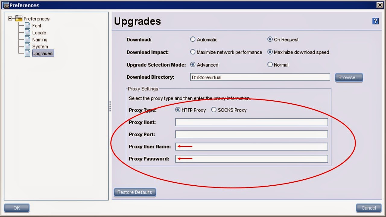
Inorder to add proxy authentication please follow below process, 

Click Help --> Preferences and enter the user name and password for authentication.

HP StoreVirtual(P4000) Storage Online upgrade proxy authentication


3PAR Remote Copy configuration using RCFC ports(CLI version)- Part 2

Please read Part1 Before you start


This is Part2 topics of 3PAR Remote Copy configuration.

2.Setting Up the Primary System for Remote Copy


Before you start make a note of Node WWNs and RCFC port WWNs for both storage arrays.

System1

Node WWN:- 2FF70002AC00ABCD
WWN of 0:2:1 :-20210002AC00ABCD
WWN of 1:2:1 :-21210002AC00ABCD


System2

Node WWN:- 2FF70002AC00CDAB
WWN of 0:2:1 :-20210002AC00CDAB
WWN of 1:2:1 :-21210002AC00CDAB

Now we can proceed,

Run "startrcopy" command to start HP 3PAR Remote Copy on the primary storage system(System1). "startrcopy" command enables remote copy, but this command requires the HP 3PAR Remote Copy Software license. Ensure you have required license installed before you start.

System1 cli% startrcopy
Issue the following commands to define a target links on the primary storage system (System1).
# creatercopytarget target_name FC node_WWN N:S:P:WWN  N:S:P:WWN
where:
• target_name —Name of the target system (System2)
FC—Defines link as an FC link
node_WWN   —WWN of the node on the target system
• N:S:P:WWN—FC adapter port on the primary system (System1), expressed as
node:slot:port, and the WWN of the peer port on the target system (System2)

System1 cli% creatercopytarget System2 FC 2FF70002AC00CDAB 1:2:1:21210002AC00CDAB

Repeat the same process on the target system (System2)

System2 cli% startrcopy
System2 cli% creatercopytarget System1 FC 2FF70002AC00ABCD 1:2:1:21210002AC00ABCD

Check the status of the remote copy configuration using showrcopy command(eg: on System1) on both 3PAR arrays.The showrcopy command displays details of the remote-copy configuration.

System1 cli% showrcopy

Remote Copy System Information
Status: Started, Normal
Target Information
Name         ID Type Status Options          Policy    
System2    2 FC   ready  2FF70002AC00CDAB mirror_config
Link Information
Target       Node  Address          Status Options
System2      0:2:1 20210002AC00CDAB Up          
System2      1:2:1 21210002AC00CDAB Up          
receive      0:2:1 20210002AC00CDAB Up          
receive      1:2:1 21210002AC00CDAB Up  

To check the links between the primary and backup systems, issue the showrcopy command on the backup system (System2):

System2 cli% showrcopy

Remote Copy System Information
Status: Started, Normal
Target Information
Name          ID Type Status Options          Policy    
System1        2 FC   ready  2FF70002AC00ABCD mirror_config
Link Information
Target        Node  Address          Status Options
System1       0:2:1 20210002AC00ABCD Up          
System1       1:2:1 21210002AC00ABCD Up          
receive       0:2:1 20210002AC00ABCD Up          
receive       1:2:1 21210002AC00ABCD Up 
         
Verify the following:
• The Status of the Target Information area is ready.
• The Status of the Link Information area is Up for all the links.

3.Creating Volume Groups for Remote Copy


Issue the following command to set up a volume group called RCPY_Group on the primary storage system (System1) with a replication mode "sync":

System1 cli% creatercopygroup RCPY_Group System2:sync

if the replication mode is to be changed to "periodic" replace "sync" with "periodic".

check the status of remote copy configuration using "showrcopy" command and verify the copy group name under "group information".
System1 cli% showrcopy

Remote Copy System Information
Status: Started, Normal
Target Information
Name         ID Type Status Options          Policy    
System2       2 FC   ready  2FF70002AC00CDAB mirror_config
Link Information
Target       Node  Address          Status Options
System2      0:2:1 20210002AC00CDAB Up          
System2      1:2:1 21210002AC00CDAB Up          
receive      0:2:1 20210002AC00CDAB Up          
receive      1:2:1 21210002AC00CDAB Up          
Group Information
Name         Target       Status   Role       Mode     Options
RCPY_Group   System2 New      Primary    Sync          
  LocalVV      ID   RemoteVV     ID   SyncStatus    LastSyncTime
Check and ensure that the newly created remote copy group is available under "group information".

To create a volume automatically on the secondary storage system,we must set associated local and remote CPGs for existing remote-copy groups,issue the "setrcopygroup" with the "cpg" subcommand and -usr_cpg and -snp_cpg options. As an initial step,the primary volume must first
be created on the source system.

System1 cli% setrcopygroup cpg -usr_cpg CPG_FC_BC System2:CPG_FC_BC -snp_cpg CPG_FC_ARC System2:CPG_FC_ARC RCPY_Group
Setting the cpg for group RCPY_Group.

On the source system, issue the "admitrcopyvv" command with the "-createvv" option.The admitrcopyvv command adds an existing virtual volume to an existing remote-copy volume
group.

System1 cli% admitrcopyvv -createvv 3PAR_POC_TPVV RCPY_Group System2:3PAR_POC_TPVV_RCPY

Now you have to start the copy group to initiate the sync.on Primary system, run "startrcopygroup"command as follows.The startrcopygroup command enables remote copy for the specified remote-copy volume group.

System1 cli% startrcopygroup RCPY_Group
Group RCPY_Group starts, task ID = 7185 

After few minutes check the copy status using showrcopy command.

System1 cli% showrcopy

Remote Copy System Information
Status: Started, Normal
Target Information
Name         ID Type Status Options          Policy    
System2       2 FC   ready  2FF70002AC00CDAB mirror_config
Link Information
Target       Node  Address          Status Options
System2      0:2:1 20210002AC00CDAB Up          
System2      1:2:1 21210002AC00CDAB Up          
receive      0:2:1 20210002AC00CDAB Up          
receive      1:2:1 21210002AC00CDAB Up          
Group Information
Name         Target       Status   Role       Mode     Options
RCPY_Group   System2 Started  Primary    Sync          
  LocalVV       ID   RemoteVV           ID   SyncStatus    LastSyncTime
  3PAR_POC_TPVV    2 3PAR_POC_TPVV_RCPY    9 Synced        NA

Thats it!! we are done with initial testing.

We can add vvols to the existing Remote Copy group or we can have multiple copy groups depending on the requirement. 

3PAR Remote Copy configuration using RCFC ports(CLI version)-Part 1

We have to consider following items first, while we configure remote copy on 3PAR storage system.

1.RCFC can be set up only on storage systems that communicate over FC storage area networks.
2.Understand the Storage area network that is used to connect the storage systems
3.The storage array ports, which are to be configured for RCFC, should be part of same zoneset

the first step is to establish zones between the RCFC ports of System1 and System2 which are to be configured for Replication.
In this demo setup, we are using Brocade SAN switches and both the systems are on the same SAN Fabric. If your systems are on different SAN Fabric and you have Brocade switches, you have to cerate LSANs to establish the connectivity between the RCFC ports.

Create RCFC zones on Fabric1

alicreate  "System1_RCFC_1_2_1", "21:21:00:02:ac:00:ab:cd"
alicreate  "System2_RCFC_1_2_1", "21:21:00:02:ac:00:cd:ab"
zonecreate   "System2_RCFC_1_2_1_System1_RCFC_1_2_1", "System1_RCFC_1_2_1;System2_RCFC_1_2_1"
cfgadd  "cfgfabric1", "System2_RCFC_1_2_1_System1_RCFC_1_2_1"
cfgsave
cfgenable  cfgfabric1
Do the zoning part on the other fabric as well(applicable only if you have redundant fabric)

alicreate  "System1_RCFC_0_2_1", "20:21:00:02:ac:00:ab:cd"
alicreate  "System2_RCFC_0_2_1", "20:21:00:02:ac:00:cd:ab"
zonecreate   "System1_RCFC_0_2_1_System2_RCFC_0_2_1", "System1_RCFC_0_2_1;System2_RCFC_0_2_1"
cfgadd  "cfgfabric2", "System1_RCFC_0_2_1_System2_RCFC_0_2_1"
cfgsave
cfgenable  cfgfabric2 
 Once the zones are ready and activated, we can start the actual RCFC configuration on 3PAR.
If these ports were not set up during the initial setup of the storage system, or if the configuration
has changed, reconfigure the ports before you set up the remote-copy.

1.Setting Up Remote-Copy Interface for RCFC


To configure the ports, use the "controlport config" command.

System1 cli% controlport config rcfc 0:2:1
Are you sure you want to run controlport config rcfc on port 0:2:1 (connection type point)?
select q=quit y=yes n=no: y
System1 cli%

System1 cli% controlport offline 0:2:1
Are you sure you want to run controlport offline on port 0:2:1?
select q=quit y=yes n=no: y

System1 cli% controlport rst 0:2:1
Are you sure you want to run controlport rst on port 0:2:1?
select q=quit y=yes n=no: y

Remember to repeat this step for all the RCFC ports on both System1 and System2.

To verify that the FC communication links have been established, issue the "showrctransport
-rcfc" command.The FC adaptor ports should appear, and the State column should display new.
System1 cli% showrctransport -rcfc
N:S:P    Peer_Node_WWN    Peer_Port_WWN State
0:2:1 2FF70002AC00ABCD 20210002AC00ABCD new
1:2:1 2FF70002AC00ABCD 21210002AC00ABCD new

To initialize the FC adaptor port, issue the controlport rcfc init command on one
system

System1 cli% controlport rcfc init -f 0:2:1

Repeat the same steps on System2 as well and verify the port status using "showrctransport
-rcfc"command.

System1 cli% showrctransport -rcfc
N:S:P    Peer_Node_WWN    Peer_Port_WWN State
0:2:1 2FF70002AC00ABCD 20210002AC00ABCD ready
1:2:1 2FF70002AC00ABCD 21210002AC00ABCD ready
Note:-If the State column displays incomplete or new, Repeat initialization step until the port is in a ready state.

Part-2 - Click to proceed!

Brocade Webtools and Java issue

After upgrading customer Brocade switches to Fab os Version 7.0.1b, we followed the Release notes and installed Oracle JRE 1.6.0 update 24 and webtools were running as expected without any issues. To stay in accordance with the security standards, we upgraded the java version to Oracle Java 7 update 51 and after that we were unable to open webtools neither in IE nor in Google Chrome.


To troubleshoot the issue, the first option was to check the installed JRE version and the best method was to issue command Java –version


Or dig in to registry and follow below path

HKEY_LOCAL_MACHINE\SOFTWARE\Wow6432Node\JavaSoft\Java Runtime Environment


Restoring java version was not a solution as customer has strict orders to follow security practices. After doing research we came to know that latest Java release supports adding IP exceptions and we decided to try that.

To do that, you have to access java control panel in windows as shown below 


Once the Java control panel is available, access “security” tab and  keep the security level High(as recommended). Go to Exception Site list and “Edit site list”


Insert your switch IP address (Webtools URL) and click “Add”.


Once done, open your browser, and try to access Webtools, there you go!.

If you have a better approach for enabling Brocade webtools access do share it under comment section. 

How to remove a brocade switch from Fabric

There are different situations you will be encountering on your daily operations. There could be a chance that the switch is beyond its capacity or an out of support model. otherwise, you may be trying to build a new fabric using least used switches in an existing fabric.
On either situations, the removal process of Brocade switches from an existing fabric is fairly same.

All that you have to do is to follow a step by step approach

1, Disable/Remove the ISLs to the switch which you want to remove
2, disconnect/migrate the cable to new switch
3, disable the switch and clear the configuration.

Lets see how can we do that!

if the switch is no longer used by any hosts or storage arrays, make sure you don't have any cables plugged in to any ports. the other step is to isolate the switch from active fabric. To do that, you can
disable the ISLs(disable the E ports)

to disable the switch, issue the command as below

SANSW01:admin> switchdisable

Once the switch is disabled, you can disable the configuration which is presently active on the switch(this step must be followed if you are going to reuse the switch). To disable an active configuration, run command as below

SANSW01:admin> cfgdisable
You are about to disable zoning configuration. This
action will disable any previous zoning configuration enabled.
Do you want to disable zoning configuration? (yes, y, no, n): [no] y
Updating flash ...

After disabling the configuration, next step is to clear the configuration so that you wont face any issues while building a new fabric. To do that issue the command as below.

SANSW01:admin> cfgclear
The Clear All action will clear all Aliases, Zones, FA Zones
and configurations in the Defined configuration.
cfgSave may be run to close the transaction or cfgTransAbort
may be run to cancel the transaction.
Do you really want to clear all configurations?  (yes, y, no, n): [no] y

Once configuration is cleared, now its time to save the settings, run the command as indicated below

SANSW01:admin> cfgsave
You are about to save the Defined zoning configuration. This
action will only save the changes on Defined configuration.
Any changes made on the Effective configuration will not
take effect until it is re-enabled.
Do you want to save Defined zoning configuration only?  (yes, y, no, n): [no] y
Updating flash ...

its Done! now your switch is free from configuration and can be used for building a new fabric.

SANSW01:admin> cfgshow
Defined configuration:
 no configuration defined

How to Enable Bottleneck detection feature in Brocade

Brocade has introduced a new Bottleneck detection feature in Brocade FOS v6.3.0 onwards.  The important thing to notice is that this feature doesn't require a license and supported on 4 Gbps, 8 Gbps, and 16 Gbps platforms. Bottleneck detection feature Monitors and reports latency and congestion bottlenecks on F_Ports and E_Ports. FOS v6.4.0 release introduced enhancements to improve the functionality of detecting device latency. 

Let's see how to enable it!

To check the status of the feature, whether it is enabled or disabled, you have to issue the command as below.

SANSW01:admin> bottleneckmon --status

Bottleneck detection - Disabled

To enable bottleneck monitoring  on  a  switch  with  alerts using  default  values for threshold and time, you have issue the command as below

SANSW01:admin> bottleneckmon --enable -alert

If the command is used without any detection parameters, default thresholds will be applied.The  congestion and Latency thresholds are expressed as a fraction between 0 and 1. The default value for congestion threshold is 0.8 and for latency, default value is 0.1
Setting a latency threshold of 0.1 and a time window of 300 seconds specifies that an alert should be  sent, when  10%  of  the  one-second samples over any period of 300 seconds were affected by latency bottleneck conditions.
Once bottleneck monitoring is enabled on a switch and -alert is  specified, if the ports on  the  configured  switch  experience latency  or congestion the  command  triggers  an SNMP alert

To fine tune the feature, --config operands is used along with following parameters,

-cthresh   Specifies  the severity threshold for congestion that triggers an alert.   The threshold indicates the percentage of one-second intervals affected  by  the  bottleneck  condition within the specified time window. 

-lthresh Specifies  the severity threshold for latency that triggers an alert. The  threshold  indicates  the percentage of one-second intervals affected by the bottleneck  condition  within the  specified  time window. 
-time Specifies  the  time  window  in seconds over which the bottleneck  conditions  is  computed and compared with the threshold. The default is 300 seconds.

-qtime Specifies  the  minimum  number  of   seconds  between  consecutive  alerts.  The default is 300 seconds. 


Eg:-
SANSW01:admin> bottleneckmon --config -alert -lthresh .2 -cthresh .9 -time 300 

To check the status
SANSW01:admin> bottleneckmon --status

Bottleneck detection - Enabled
==============================
Switch-wide sub-second latency bottleneck criterion:
====================================================
Time threshold                 - 0.800
Severity threshold             - 50.000
Switch-wide alerting parameters:
================================
Alerts                         - Yes
Latency threshold for alert    - 0.200
Congestion threshold for alert - 0.900A
veraging time for alert       - 300 seconds
Quiet time for alert           - 300 seconds

To display the number of ports affected by bottleneck conditions issue the command as below:

SANSW01:admin> bottleneckmon --show

To disable bottleneck monitoring on all ports in a chassis:

SANSW01:admin> bottleneckmon --disable
Admin Helpline™ © , All Rights Reserved.
Privacy Policy